Logic Gates
AND Gate
Functionality
It will output High[1] only if all the inputs to the gate are High[1]. If any of the inputs to the AND gate is Low, it will output Low[0]. The function can be extended to any number of inputs.
Symbol

Boolean Expression
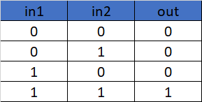
Truth Table
Implementation using Diode


OR Gate
Functionality
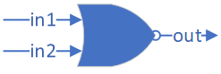
It will output Low[0] only if all the inputs to the gate are Low[0]. If any of the inputs to the OR gate is High, it will output High[1]. The function can be extended to any number of inputs.
Symbol

Boolean Expression
Truth Table

Implementation using Diode


NOT Gate
Functionality
It will invert the input being applied.
Symbol

Boolean Expression
Truth Table

NAND Gate
Functionality
It will output Low[0] only if all the inputs to the gate are High[1]. If any of the inputs to the AND gate is Low, it will output High[1]. Nand gate consists of an AND gate followed by a NOT gate[inverter].
Symbol

Boolean Expression
Truth Table

NOR Gate
Functionality
It will output High[1] only if all the inputs to the gate are Low[0]. If any of the inputs to the OR gate is High, it will output Low[0]. NOR gate consists of an OR gate followed by a NOT gate[inverter].
Symbol
Boolean Expression
Truth Table

XOR Gate
Functionality
It will output High[1] if both the inputs are different, else will output Low[0].
Symbol

Boolean Expression
Truth Table

XNOR Gate
Functionality
It will output High[1] if both the inputs are same, else will output Low[0]. XNOR gate consists of a XOR gate followed by a NOT gate.
Symbol

Boolean Expression
Truth Table

Universal Gates
Nand and Nor gates are called as universal gates, as we could implement other basic gates[AND,OR,NOT] just by using nand or nor gates.
Basic Gates Implementation using NAND

1.NOT using NAND

As NOT gate have only 1 input and both not and nand have inverted version at the output, we could simply short 2 inputs of the NAND gate to make it behave as a NOT gate.
Below is the implementation,

2.AND using NAND

If we look at the truth table of both the gates, we could clearly
understand that the output of AND gate is just an inverted version of NAND
gate's. So we can implement an AND gate by inverting the NAND gate's output.
Since we have to implement the whole AND gate by NAND itself, we need an
inverter also in the form of NAND gate.
Below is the implementation,

3.OR using NAND

As per the DE Morgan's theorem,
Hence, If we invert the inputs of the NAND gate output will be A + B.
Below is the implementation,


Very usefull information
ReplyDeleteThanks😊